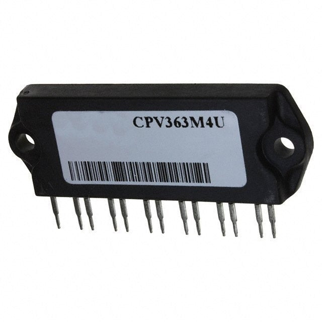
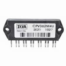

CPV362M4U
Regular price
Rs.0.00
Quick Search:


The CPV362M4U is an UltraFast IGBT SIP module designed for three-phase inverter and motor-drive applications. It features a collector-to-emitter voltage rating of 600 V and offers continuous collector currents of 7.2 A at 25°C and 3.9 A at 100°C. The module is capable of handling pulsed collector currents up to 22 A, making it suitable for mid-voltage power conversion tasks.
Constructed with HEXFRED™ soft ultrafast diodes and an insulated-metal-substrate (IMS-2) package, the CPV362M4U ensures low thermal resistance and simplifies PCB mounting. The module's thermal metrics include a junction-to-case thermal resistance of approximately 5.5 °C/W for each IGBT and a case-to-sink value of 0.10 °C/W. It also provides an isolation rating of 2500 VRMS for safety in industrial systems.
Optimized for high switching performance, the CPV362M4U supports operating frequencies beyond 5 kHz. In typical motor-drive scenarios, it delivers approximately 4.6 A RMS per phase, equating to about 1.3 kW total output at a modulation depth of 115%. These characteristics make it a reliable and efficient choice for commercial drives, small industrial inverters, and other embedded power-electronics applications.
| Specification | Value | Conditions / Notes |
|---|---|---|
| Collector-to-Emitter Voltage (VCES) | 600 V | Breakdown rating. |
| Continuous Collector Current (IC) | 7.2 A @ TC = 25°C; 3.9 A @ TC = 100°C | Thermal case-dependent ratings. |
| Pulsed Collector Current (ICM) | 22 A | Pulsed capability. |
| Maximum Power Dissipation (PD) | 23 W @ TC = 25°C (9.1 W @ TC = 100°C) | Datasheet thermal limits. |
| VCE(on) (typ / max) | ~1.70 V / 1.95 V | Measured at VGE = 15 V. |
| Gate-to-Emitter Voltage (VGE) | ±20 V | Absolute rating. |
| Isolation Voltage | 2500 VRMS (1 minute) | Safety isolation. |
| Thermal Resistance (junction-to-case) | IGBT: ~5.5 °C/W; Diode: ~9.0 °C/W | One device in conduction. |
| Case-to-Sink Thermal Resistance | 0.10 °C/W | Flat, greased surface. |
| Diode Forward Current (IF) | 3.4 A (continuous @ TC = 100°C); 22 A (max) | Complementary diode ratings. |
| Gate Charge (Qg) | 31–47 nC | Typical switching data at specified conditions. |
| Switching Losses (Eon / Eoff) | 0.13 mJ / 0.07 mJ | Energy losses include "tail" and diode reverse recovery. |
| Package | IMS-2 SIP module, PCB mount, 13-pin | Fully isolated IMS package for compact mounting. |
| Typical Application Performance | ~4.6 A RMS per phase (≈1.3 kW total) | TC = 90°C, TJ = 125°C, Vdc = 360 V, PF = 0.8, modulation depth 115%. |
We dispatch all orders through Leopard Courier and TCS, while bulk or heavy shipments are sent via cargo (bilty) for safer handling and better rates. Standard delivery time is 2–3 working days for both courier and cargo deliveries, depending on your location. Orders are dispatched within 24 hours after payment confirmation, and the tracking number is shared on WhatsApp once shipped. Shipping charges depend on parcel weight and destination, and may be waived for bulk or corporate orders. Please ensure your contact details and address are accurate to avoid delays. For urgent delivery or specific shipping requirements, contact us directly on WhatsApp at 0303 56888 44.
Here’s some of our most similar products people are buying. Add it to cart now
